Understanding the Refrigeration Cycle: A Step-by-Step Guide for F-Gas Candidates
Master the four core stages of the vapour-compression refrigeration cycle and learn how superheat, subcooling and saturation underpin safe F-Gas practice.
Why the Refrigeration Cycle Matters for F-Gas Engineers
If you are working towards your City and Guilds 2079 certificate, the vapour-compression refrigeration cycle is the single most important concept to internalise. Every practical task you will be assessed on — recovery, charging, leak checking, brazing repairs and commissioning — relies on understanding where the refrigerant is, what state it is in, and why. Current F-Gas rules expect qualified personnel to handle fluorinated greenhouse gases competently, and competence starts with the fundamentals.
This guide walks through the cycle exactly as it operates in a standard air-conditioning system, mirroring the structure used in F-Gas training materials and the AC Service Tech tutorial that inspired it.
The Two Pressure Zones

Every direct-expansion system is divided into two pressure zones, separated by two key components:
- The compressor — sits at the top of the system, raising pressure and temperature.
- The metering device — typically a thermostatic expansion valve (TXV), electronic expansion valve (EEV) or fixed orifice, sits lower down and drops pressure into the evaporator.
“You have two items that separate the low pressure and the high pressure on this system — one is the compressor up high, and the other is the metering device down low.”
Everything between the compressor discharge and the metering device inlet is the high side. Everything between the metering device outlet and the compressor suction is the low side. Knowing which zone you are working on dictates which gauge port you connect to, how you interpret your readings and how you handle the refrigerant under F-Gas containment rules.
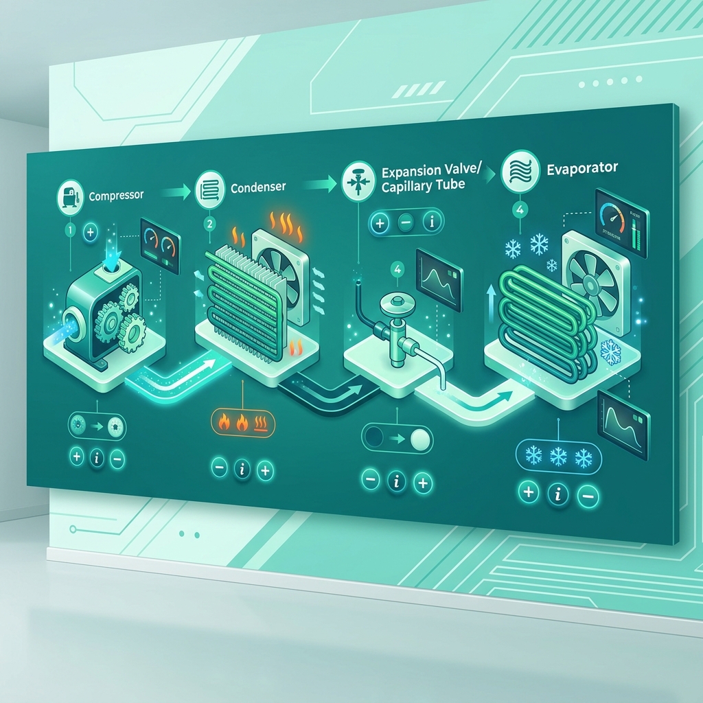
Stage 1: Compression
The cycle starts with low-pressure, low-temperature vapour entering the compressor suction. Inside the compressor, mechanical work raises the refrigerant to high pressure and high temperature vapour — in fact, the discharge line is the hottest point on the entire system.
For F-Gas candidates, this matters because:
- Discharge temperature is a key health indicator for the compressor.
- Overheated discharge gas is a common symptom of low charge, restricted airflow or a faulty metering device.
- Discharge lines must never be vented to atmosphere; deliberate release of fluorinated gases is prohibited.
Stage 2: Condensation and Subcooling
The hot vapour leaves the compressor and enters the condenser coil, where it begins rejecting heat to ambient air (or water in chilled-water systems).
Three distinct regions exist inside the condenser:
| Region | State | What is happening |
|---|---|---|
| Inlet section | Superheated vapour | Sensible cooling down to saturation |
| Middle section | Saturated mix (vapour and liquid) | Latent heat rejection — the bulk of energy transfer |
| Outlet section | Subcooled liquid | Sensible cooling below saturation |
“The saturated state is where it’s transferring most of its energy at.”
Once the refrigerant reaches the outlet, it is a pure liquid that is cooler than its saturation temperature. The difference between the saturation temperature and the actual liquid line temperature is the subcooling value.
A healthy subcooling reading (typically 8 to 12 K on many split systems, but always check manufacturer data) tells you:
- The condenser has rejected the expected amount of heat.
- There is a solid column of liquid feeding the metering device.
- The charge is broadly correct on a TXV system.
Stage 3: The Filter Drier and Metering Device
After the condenser, the liquid passes through the filter drier. Its job is straightforward:
- Absorb residual moisture using a desiccant such as molecular sieve or activated alumina.
- Trap fine particulates.
- It has a fixed moisture capacity — once saturated, it must be replaced. Always fit a new drier after opening a system for repair, as required by best practice and reinforced in City and Guilds 2079 skill groups covering installation and servicing.
The liquid then arrives at the metering device, where the magic of the cycle happens. The device permits only a small, controlled flow of refrigerant into the evaporator. Because pressure drops sharply, saturation temperature drops with it.
“If you decrease pressure, then temperature will decrease.”
The resulting mixture entering the evaporator is roughly 80 per cent low-pressure liquid and 20 per cent flash gas — a cold, two-phase mixture ready to do useful work.
Stage 4: Evaporation and Superheat
Inside the evaporator, the cold refrigerant absorbs heat from the conditioned space. The coil contains the same three regions as the condenser, but in reverse:
- Inlet — cold liquid and a small amount of flash gas.
- Middle — saturated mix, where most of the heat absorption (latent) occurs.
- Outlet — superheated vapour, fully boiled off and slightly warmed.
Exam tip: The point in the evaporator where the last droplet of liquid boils off is the start of superheat. The temperature rise between that point and the suction service valve is the total superheat.
Measuring superheat at the service valve next to the compressor gives you the total superheat figure used to verify charge on fixed-orifice systems and to confirm correct TXV operation on others. Too little superheat risks liquid floodback to the compressor — a leading cause of catastrophic compressor failure. Too much superheat means the evaporator is starved, reducing capacity and overheating the compressor.
Putting the Cycle Together
To recap the full loop:
- Low-pressure, low-temperature vapour enters the compressor.
- High-pressure, high-temperature vapour leaves the compressor and enters the condenser.
- Heat is rejected; the refrigerant passes through superheated, saturated and subcooled regions.
- The liquid passes through the filter drier and then the metering device.
- A low-pressure, low-temperature two-phase mixture enters the evaporator.
- Heat is absorbed; the refrigerant boils, becomes saturated, then superheated.
- Low-pressure, low-temperature vapour returns to the compressor — and the cycle repeats.
Linking the Cycle to F-Gas Duties
Understanding the cycle is not just academic — it is woven through every practical requirement of the F-Gas Regulation:
- Article 3 (Prevention of emissions): You cannot prevent emissions if you do not understand where refrigerant sits, what pressure it is at, and how to recover it safely.
- Article 4 (Leak checks): Routine leak checks rely on interpreting pressure, temperature and superheat/subcooling values against expected operating envelopes.
- Article 8 (Recovery): Knowing the high side from the low side is essential to attaching recovery equipment correctly.
- Annex I refrigerants: GWP figures dictate quota and reporting, but practical handling still depends on the same thermodynamic cycle described above.
How F-Gas Exam Prep Fits Into This
The F-Gas Exam Prep app is built precisely for the kind of fundamentals covered in this article. It includes:
- 460+ exam questions spanning every City and Guilds 2079 skill group, from refrigeration fundamentals through to safe handling of flammable A2L refrigerants.
- Mock exams that mirror the structure and timing of the real City and Guilds 2079 assessment, so there are no surprises on the day.
- AI voice challenges that let you practise answering questions verbally — ideal when you are revising in the van between calls.
- Detailed explanations for every answer, so when you get a question on superheat, subcooling or the saturated state wrong, you learn exactly why and how the cycle behaves.
Master the refrigeration cycle and the rest of your F-Gas study becomes a series of logical extensions rather than disconnected facts. Get this foundation right, and your practical assessment will feel like second nature.
Start Practising Today
Download the F-Gas Exam Prep app and study with 460+ practice questions, mock exams, and detailed explanations.