How to Read Superheat and Subcooling: A Practical Guide for F-Gas Technicians
Learn the simple gauge-minus-line rule for measuring superheat and subcooling, with worked examples and tips for your City & Guilds 2079 assessment.
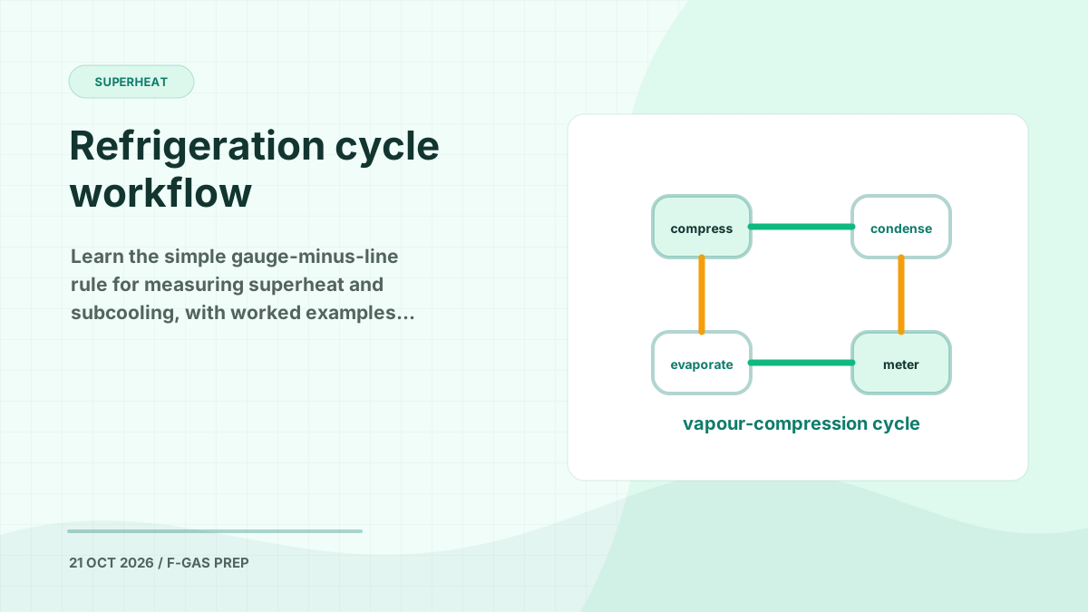
Ask any experienced refrigeration engineer what they got muddled about in their first year and plenty will admit it: which reading is superheat and which is subcooling, and which way round the subtraction goes. The video this post is based on, from Word of Advice TV, deals with exactly that. It skips the theory and the fault-finding and just shows you how to take the two readings, step by step.
That makes it a good refresher for anyone preparing for the City & Guilds 2079 practical assessment. Taking superheat and subcooling readings is a basic commissioning skill, and assessors will expect you to do it confidently and safely.
Connecting Your Manifold Gauges Correctly

The video starts with the basics: low side and high side.
- Low side (blue hose, blue gauge): connects to the suction line, which is the larger diameter pipe returning vapour to the compressor.
- High side (red hose, red gauge): connects to the high pressure side of the system.
The presenter makes a point that applies just as much in the UK as anywhere else:
“I like to make sure that all my fittings are on there securely. That way, when I put my hoses on, refrigerant is not spewing out if they’re loose.”
He also notes that the access caps should have their O-rings in place. If the Schrader valve core is weeping slightly, a sealed cap is your secondary seal. A missing O-ring is a possible leak path, so replace any caps that have lost theirs.
Key point: Under Article 3 of Regulation 517/2014, operators and engineers must take precautions to prevent leakage. Checking access valve cores and caps is part of that duty, and leaving caps off or unsealed is poor practice that an assessor will notice.
He recommends low-loss fittings, and you should take that advice seriously. Low-loss couplers trap refrigerant in the hose when you disconnect, so far less escapes each time you connect or remove your gauges. They cost more, but they cut emissions, protect your hands and look professional in an assessment.
He also mentions wearing gloves when handling refrigerant to avoid cold burns. Eye protection matters just as much. Liquid refrigerant flashing off can cause serious injury to unprotected eyes.
Equalised Pressures and Purging: A UK Perspective
With the system switched off and the gauges fitted, the video shows both sides equalised at the same pressure. That is what you should see on a system that has been off for a while. If the pressures do not equalise, something is restricting flow, so take note of it.
Before starting the unit, the presenter “cracks” each hose to purge air out. His reasoning is sound: non-condensables in the system raise head pressure and cut efficiency. In the UK, though, how you clear air from your hoses matters.
Important: Article 3(1) of Regulation 517/2014 prohibits the intentional release of fluorinated greenhouse gases where it is not technically necessary for the intended use. Venting refrigerant from your hoses as routine practice will not go down well in a City & Guilds 2079 assessment.
Better practice:
- Use low-loss fittings, so hoses hold minimal air when you connect them.
- Evacuate your hoses and manifold with a vacuum pump before connecting to the system, where practical.
- If you must purge, use the smallest possible amount of refrigerant through a properly closed manifold.
Also note that the system in the video runs on R22. R22 is an HCFC, so it is controlled under the Ozone Depleting Substances regulations rather than the F-Gas Regulation. Using virgin or reclaimed R22 to service systems has been banned since 2015. You will still come across it on older plant, but you cannot top it up. For the exam, be clear on the difference between HCFCs (ozone-depleting) and HFCs (F-gases with high GWP).
The Simple Formula: L − G and G − L
This is the core of the video, and the presenter’s memory aid works well:
“I would write G minus L equals SC… gauge minus line will equal my subcooling reading. And for the superheat, it would be L minus G equals SH.”
So:
| Measurement | Where | Formula |
|---|---|---|
| Superheat (SH) | Low side, at the suction line | Line temp − Gauge (saturation) temp |
| Subcooling (SC) | High side, at the liquid line | Gauge (saturation) temp − Line temp |
“Gauge temperature” here means the saturation temperature read from the refrigerant-specific scale on your gauge (or your digital manifold, or a P-T chart), not the pressure. As the presenter says, you need a gauge or chart for the refrigerant in the system you are working on.
Exam tip: Superheat is always measured on the vapour side, where the actual temperature is above saturation. Subcooling is always measured on the liquid side, where the actual temperature is below saturation. If you know which state the refrigerant is in, you will always get the subtraction the right way round.
Reading the Pressure-Temperature Relationship

The method relies on the fixed pressure-temperature relationship of a saturated refrigerant. At any given pressure, a refrigerant that is boiling or condensing sits at one specific temperature. Your gauge converts the pressure into that saturation temperature.
Once the system has stabilised, you compare the saturation temperature with the actual pipe temperature, taken with a pipe clamp thermometer or, less reliably, an infrared thermometer. The difference tells you how far the refrigerant has moved past its saturation point.
A note on zeotropic blends such as R407C or R454B: these have temperature glide. Use the dew point for superheat calculations and the bubble point for subcooling. This often comes up in exam questions.
Worked Example from the Video
Once the unit started, the suction pressure dropped and the discharge pressure rose, as expected. The presenter let it run for 5–10 minutes so the readings could settle. Don’t skip this step: readings taken too early are unreliable.
The video works in Fahrenheit, but UK practice and the 2079 assessment use Kelvin (K) for temperature differences. Here are the figures from the video, converted:
Superheat:
- Suction line temperature: 48°F (≈ 8.9°C)
- Saturation temperature from gauge: 40°F (≈ 4.4°C)
- Superheat = 8°F ≈ 4.4 K
Subcooling:
- Saturation temperature from high side gauge: 82°F (≈ 27.8°C)
- Liquid line temperature: 72°F (≈ 22.2°C)
- Subcooling = 10°F ≈ 5.6 K
The presenter recommends placing the clamp a few inches from the service valve. Make sure the pipe surface is clean and the probe is in good contact. Ideally, insulate over the probe so ambient air doesn’t distort the reading. One detail to be careful with: the video calls the high side “discharge”, but subcooling must be measured on the liquid line, not the hot gas discharge line. On a split system, that is usually the smaller pipe at the outdoor unit service valve.
Whether these figures are “good” depends on the system type, the metering device and the manufacturer’s data. Always check against the manufacturer’s commissioning figures rather than general rules of thumb.
Why This Matters for Your F-Gas Assessment
Superheat and subcooling readings come up in several areas of the City & Guilds 2079 syllabus:
- Commissioning and system performance: confirming the system is working within its design parameters.
- Charge assessment: low superheat with high subcooling can mean overcharge, and high superheat with low subcooling often means undercharge or a leak.
- Leak checking: under Article 4 of Regulation 517/2014, a refrigerant shortage found through performance readings should lead you to a proper leak check.
- Safe refrigerant handling: connecting and disconnecting gauges with as little emission as possible.
Category I certification covers all of these activities. Even Category II engineers, who can do leak checks on smaller systems without breaking into the circuit, must understand how performance readings show refrigerant loss.
How F-Gas Exam Prep Fits Into This
Knowing L − G and G − L is a good start, but the 2079 exam will test whether you can apply it: reading P-T relationships, picking the right point on a blend’s glide, and working out what an abnormal reading means for the system’s charge.
The F-Gas Certification Exam Prep app is built to help you practise exactly that:
- 370+ exam questions across all City & Guilds 2079 skill groups, including system performance, commissioning and refrigerant handling.
- Mock exams that mirror the real City & Guilds 2079 format, so you know what to expect on the day.
- AI voice challenges for interactive revision. Talk through superheat and subcooling scenarios as if an assessor were questioning you.
- Detailed explanations for every answer, so you learn the reasoning, not just the correct letter.
Download F-Gas Exam Prep on iOS or Android and go into your assessment ready.
Start Practising Today
Download the F-Gas Exam Prep app and study with 460+ practice questions, mock exams, and detailed explanations.

