The Vapour Compression Refrigeration Cycle Explained: A Technically Correct Walkthrough
A technically accurate breakdown of the vapour-compression cycle — the four components, four processes, and COP/EER efficiency, for your F-Gas assessment.
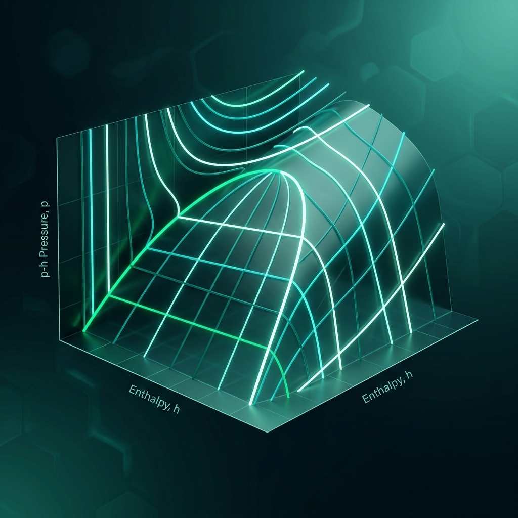
If you are preparing for your City & Guilds 2079 F-Gas assessment, there is one piece of theory you simply cannot avoid: the vapour compression refrigeration cycle. It is the backbone of virtually every air conditioner, refrigerator, chiller and heat pump you will ever work on, and the examiners know it. This post walks through the cycle the way an assessor would want you to understand it — component by component, process by process — drawing on an excellent technical explainer from the AEC Learn channel.
The Four Essential Components
Every vapour compression system, from a domestic fridge to an industrial chiller, is built around the same four components:
- Compressor — raises the pressure and temperature of the refrigerant vapour
- Condenser — rejects heat to the surroundings, condensing vapour to liquid
- Expansion valve (or capillary tube/TEV) — drops the pressure sharply
- Evaporator — absorbs heat from the space being cooled, boiling the liquid back to vapour
“The refrigerant moves through these components in a closed loop, changing pressure, temperature, and phase to move heat from one place to another.”
That single sentence is worth memorising. Refrigeration does not create cold — it moves heat, and it does so by exploiting the relationship between pressure and boiling point. Master that idea and the rest of the cycle falls into place.
The Four Thermodynamic Processes
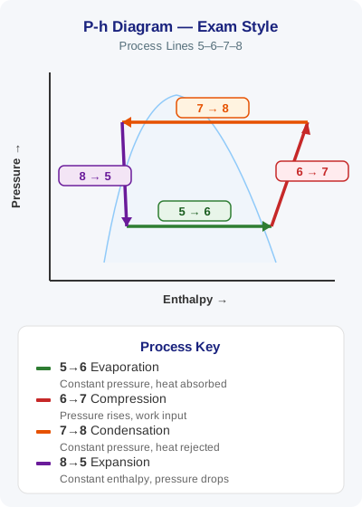
Engineers visualise the cycle on pressure-enthalpy (p-h) and temperature-entropy (T-s) diagrams, using four numbered state points. You should be able to describe the refrigerant’s condition at every point.
Compression (Point 1 to 2)
The refrigerant enters the compressor as a low-pressure, low-temperature saturated vapour. The compressor performs (ideally isentropic) compression, raising both pressure and temperature significantly. By point 2 the refrigerant is a high-pressure, high-temperature superheated vapour.
Condensation (Point 2 to 3)
The hot vapour enters the condenser and releases heat to the surroundings — typically ambient air or cooling water. This is isobaric heat rejection: the pressure stays constant while the refrigerant condenses from vapour to liquid. By point 3 you have a high-pressure saturated liquid.
Expansion (Point 3 to 4)
The liquid then passes through the expansion valve or capillary tube. This is an isenthalpic process — enthalpy remains constant while the pressure drops sharply.
“As a result, part of the liquid flashes into vapour, cooling the mixture. At point 4, we have a low-pressure liquid-vapour mix, ready to absorb heat.”
That “flash gas” effect catches a lot of candidates out. No heat is added or removed in the valve itself; the temperature drop comes purely from the pressure reduction and partial vaporisation.
Evaporation (Point 4 to 1)
Finally, the cold liquid-vapour mixture enters the evaporator and absorbs heat from the space or product being cooled. This is another isobaric process, but this time it is heat absorption. The liquid vaporises completely, and by point 1 the refrigerant is back to a low-pressure vapour — ready to start the cycle again.
Key point: Compression increases pressure and temperature. Condensation removes heat at constant pressure. Expansion drops pressure and temperature without changing enthalpy. Evaporation absorbs heat, turning liquid into vapour. Then the cycle repeats.
Cooling Mode vs Heat Pump Mode
The vapour compression cycle has two primary applications, and the elegant part is that they are the same cycle run in opposite directions:
- Cooling mode — the system absorbs heat from the indoor environment and rejects it outside. This is the basic principle behind air conditioners and refrigerators.
- Heating mode (heat pump) — the cycle is reversed: heat is absorbed from outdoor air and released indoors, even when the outside temperature is low.
So how does a modern split system switch between the two? The answer is the reversing valve — a four-way valve installed near the compressor:
- In cooling mode, it directs hot, high-pressure refrigerant from the compressor to the outdoor coil, which acts as the condenser.
- In heating mode, it reroutes the flow so the indoor coil becomes the condenser and the outdoor coil becomes the evaporator.
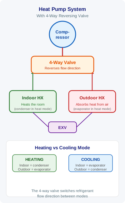
Exam tip: Examiners like to ask which coil is acting as the condenser in heating mode. Remember: the condenser is always the coil rejecting heat — indoors in heating mode, outdoors in cooling mode.
Measuring Efficiency: COP and EER
You will see two efficiency metrics again and again in both the exam and manufacturer literature:
| Metric | Definition | Units |
|---|---|---|
| COP (cooling) | Heat removed from the low-temperature environment ÷ compressor work input | Dimensionless |
| COP (heating) | Heat delivered to the high-temperature environment ÷ compressor work input | Dimensionless |
| EER | Cooling output (BTU/h) ÷ electrical power input (W) | Imperial-based ratio |
A well-optimised system maximises heat absorption while minimising compressor work — in other words, a high COP or EER means a more efficient system. In practice, the choice of refrigerant, compressor type and heat exchanger design all affect performance and, crucially for F-Gas work, environmental impact.
This is where the theory meets F-Gas compliance. Phase-down rules and product bans are pushing the industry towards lower-GWP refrigerants, and understanding how refrigerant choice interacts with cycle efficiency is exactly the kind of joined-up knowledge that separates a competent certificated engineer from someone who has just memorised answers.
The Ideal Cycle vs the Real World
On paper, the cycle follows a clean, ideal path on the thermodynamic diagrams. In practice, real systems deviate from the ideal, primarily due to irreversibilities:
- Pressure drops as the refrigerant flows through pipes, coils and system components
- Unwanted heat transfer to or from the surroundings along the pipework
These effects reduce overall efficiency and shift the actual cycle path away from the ideal curves on p-h or T-s diagrams. As a working engineer, this is why measured superheat, subcooling and operating pressures never quite match textbook values — and why diagnosing a system means understanding what the ideal should look like so you can spot meaningful deviations.
Important: Excessive pressure drop or abnormal heat gain on the suction line is not just an efficiency problem — it can mask or mimic the symptoms of refrigerant undercharge caused by leakage. Being able to distinguish a genuine leak from a system design issue is a core professional skill.
Why This Matters for Your F-Gas Exam
The vapour compression cycle sits squarely in Skill Group 1 of the City & Guilds 2079 syllabus — basic thermodynamics. The theory paper expects you to know:
- The function of each of the four components
- The state of the refrigerant (pressure, temperature, phase) at each point in the cycle
- The meaning of isobaric, isentropic and isenthalpic processes
- How pressure relates to saturation temperature
- What COP represents and why it matters
It also underpins the practical assessments: you cannot meaningfully interpret gauge readings, check superheat and subcooling, or carry out leak diagnosis (Skill Group 3) without a solid mental model of the cycle. Whether you are sizing equipment, analysing loads or selecting refrigerants under the F-Gas phase-down, this cycle is at the core of it all.
How F-Gas Exam Prep Fits Into This
Understanding the refrigeration cycle is one thing; being able to answer exam questions on it under time pressure is another. That is exactly what the F-Gas Exam Prep app is built for:
- 460+ exam questions covering all skill groups, including a dedicated bank on refrigeration fundamentals and the vapour compression cycle
- Mock exams that mirror the real City & Guilds 2079 format, so the structure and timing hold no surprises on assessment day
- AI voice challenges for interactive revision — explain the four processes out loud and have your understanding tested, just like a verbal assessment
- Detailed explanations for every answer, so when you get a question on flash gas or isenthalpic expansion wrong, you learn why — not just the correct letter
Work through the Refrigeration Fundamentals topic first, then test yourself with a mock exam. If you can confidently trace the refrigerant from point 1 to point 4 and back — naming the pressure, temperature and phase at each step — you are well on your way to passing your F-Gas assessment.
Start Practising Today
Download the F-Gas Exam Prep app and study with 460+ practice questions, mock exams, and detailed explanations.